Registruokitės, kad atrakintumėte savo išskirtines B2B kainas ir pradėtumėte apsipirkinėti. Užsiregistruokite dabar!
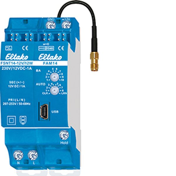
RS485 bus wireless antenna module
Yra sandėlyje: Ne
Pardavėjo atsargos: Ne
Minimalus užsakymo kiekis: 1
Kaina (be PVM):
102,33 €
EAN: 4010312313695
MPN: 30014000
Pakuotė: 1
Numatomas pristatymo laikas į mūsų sandėlį (apytiksliai):
2-4 weeks
Technical Information
| Prekės būklė | Nauja |
| Gamintojo pavadinimas | RS485 bus wireless antenna module |
| Prekės ženklas | ELTAKO |
| Kategorijos |
Jutikliai
|
| Kilmės šalis | CN |
| Suderintos sistemos kodas | 8526 9200 00 |
| Montavimo metodas | DRA |
| Nustatyta įtampa | 230 V |
| Su ekranu | No |
| EIB / KNX magistralės sistema | No |
| Magistralės sistemos radijo dažnis | Yes |
| „Powernet“ magistralės sistema | No |
| Modulinių tarpų skaičius plotyje | 2 |
| Kitos maršrutinės sistemos | Nėra |
| Nuosekliųjų sąsajų skaičius | 1 |
| LON magistralinė sistema | No |
| Integruotas DCF laikrodis | No |
| Integruotas GSM modemas | No |
| Integruotų išeigos kanalų skaičius | 126 |
| Integruotų įeigos kanalų skaičius | 128 |
| KNX radijo magistralės sistema | No |
Pakavimo informacija
| Pakavimo lygis 1 | 4010312313695, 4010312313695 |
| Pakavimo lygis 2 | 4010312313695 |
Atsisiuntimai
Aprašymas
Wireless antenna module for the Eltako RS485 bus with exchangeable antenna. With enclosed power supply FSNT14-12V/12W. Bidirectional. Encrypted wireless. Only 0.8 watt standby loss. If required, a wireless antenna FA250 or FA200 can be connected. Modular device for DIN-EN 60715 TH35 rail mounting. 1 module = 18mm wide, 5 mm deep. Supply voltage 12V DC. Connection to the Eltako RS485 bus. Bus wiring and power supply with jumpers. The delivery includes 1 power supply FSNT14-12V/12W, 1 Spacer DS14, 2 terminators with printing Ω, 1/2 module, 3 jumpers 1 module (including 1 spare), 1 jumper 1,5 TE, 2 jumpers 1/2 module (including 1 spare) and 1 jumper installation tool SMW14. If the power supply is subjected to a load of more than 4W, a ventilation distance of ½ to neighboring devices must be maintained on the left side. With a load greater than 6W, a ½ ventilation gap is also required between the FSNT14 and the FAM14 with the DS14 spacer. A DS14 spacer and a long jumper are therefore included. If the total power requirement of a Series 14 bus system is higher than 10W, an additional FSNT14-12V/12W must be used for every 12W of additional power. Optionally, 12V DC can also be supplied at the GND/+12V terminals. The wireless antenna module FAM14 receives and tests all signals from wireless transmitters and repeaters within its receiving range. These are transmitted via an RS485 interface to RS485 bus switching actuators connected in series: Up to 126 channels can be connected to the Eltako RS485 bus. Bus cross wiring and power supply with jumper. The attached second terminator should be plugged to the last actuator. You can teach in up to 32 encrypted sensors. Mini USB to connect to a PC, to create an equipment list, to configurate the actuators using the PC tool PCT14 and for data backup. A QR code for downloading the PCT14 from the Eltako homepage www.eltako.com is included with the FAM14. Gateways FGW14, FGW14-USB, FGW14W-IP and FGW14WL-IP are connected to the Hold terminal if following connections to the RS484 bus are present: with a PC over an RS232 bus, with up to 3 radio receiver modules FEM with a Sub Bus RS485 or with LAN/WLAN. The FTS14EM, FTS14TG and FWG14MS are also connected to the Hold terminal. The lower rotary switch is required to teach in encrypted sensors and can be turned to AUTO 1 in operation. Unencrypted sensors need not be taught-in in the FAM14. With the upper rotary switch BA 10 different operating modes can be set as described in the operating instructions. The upper LED displays all perceived wireless commands in the reception area by short flickering. The bottom LED lights up green if a connection from the PC tool PCT14 to the FAM14 was created. When reading or writing date the LED flickers green. The green LED goes out if the connection from the PC tool PCT14 to the FAM14 was terminated.
Priedas

In stock: No
ELTAKO
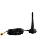
Wireless antenna with 250cm cable, black
26,29 €
EAN: 4010312300244
MPN: 30000550
Pakuotė: 1

In stock: No
ELTAKO
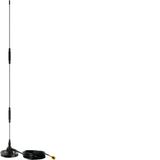
High-performance receive antenna with 200cm cable
63,91 €
EAN: 4010312303306
MPN: 30000551
Pakuotė: 1

In stock: No
ELTAKO
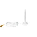
Wireless antenna with 250cm cable, grey white
25,01 €
EAN: 4010312317051
MPN: 30000553
Pakuotė: 1

