Registreeru, et avada oma eksklusiivsed B2B hinnad ja alustada ostlemist. Registreeru kohe!
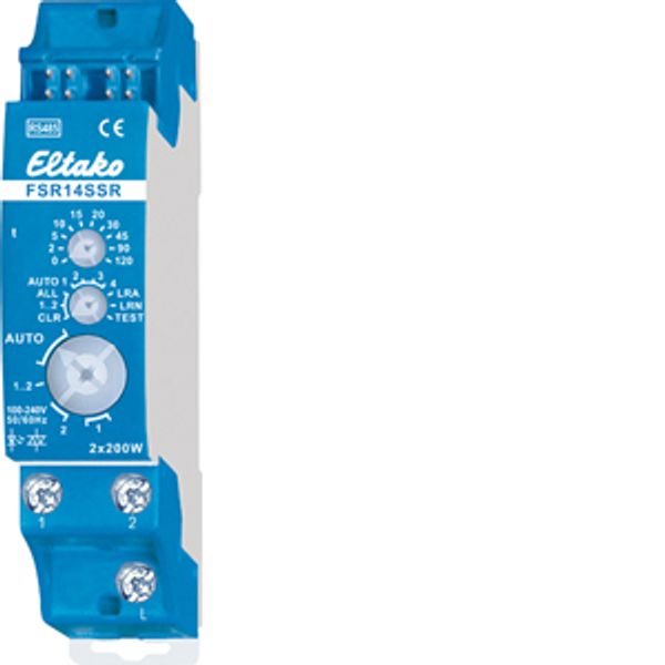
RS485 bus actuator 2-channel impulse switch with integrated relay function noiseless
Laos: Ei
Hankija laovaru: Ei
Minimaalne tellimuse kogus: 1
Hind (ilma KM-ta):
52,07 €
EAN: 4010312313893
MPN: 30014020
Pakend: 1
Hinnanguline tarneaeg meie laos (umbes):
Päringu alusel
Technical Information
| Toote seisukord | Uus |
| Tootja nimi | RS485 bus actuator 2-channel impulse switch with integrated relay function noiseless |
| Bränd | ELTAKO |
| Kategooriad |
Andurid
|
| Päritoluriik | CN |
| Harmoneeritud süsteemi kood | 8526 9200 00 |
| Paigaldusviis | DRA (DIN liistule) |
| Väljundvõimsus | 400 W |
| Tunnus-talitluspinge | 12 V |
| Siinisüsteem KNX | No |
| Raadiosageduslik siinisüsteem | Yes |
| Siinisüsteem Powernet | No |
| Suurim lülitusvõimsus | 400 W |
| Siiniühendusega | Yes |
| Suurim lülituskontaktide arv | 2 |
| Laius mooduli arvudes | 1 |
| Muud siinisüsteemid | Puudub |
| Siinisüsteem LON | No |
| C-koormus | - |
| Eri faaside ühendamine | No |
| Lokaaljuhtimine/käsijuhtimine | No |
| Kaitseaste (IP) | IP20 |
| LED näidikuga | No |
| Laiendusmoodulitega | No |
| Siinisüsteem KNX radio | No |
| Raadiosageduslik, kahesuunaline | Yes |
| Eemaldatav siini moodul | Yes |
| Max. switching power LED | 400 W |
Pakendamise üksikasjad
| Pakkimistase 1 | 4010312313893, 4010312313893 |
| Pakkimistase 2 | 4010312313893 |
| Pakkimistase 3 | 4010312313893 |
Allalaadimised
Kirjeldus
Noiseless 2-channel impulse switch with integrated relay function, 230V LED lamps up to 400W, incandescent lamps 400 watts. 2 solid state relays not potential free. Bidirectional. Only 0.1 watt standby loss. Modular device for DIN-EN 60715 TH35 rail mounting. 1 module = 18mm wide, 58mm deep. Connection to the Eltako-RS485 bus. Bus cross wiring and power supply with jumper. If both relays of the FSR14 are switched on, a power of 0.4 watts is required. The rated switching capacity of 400W is applied for one contact and also for the sum of the two contacts. The parallel connection of multiple devices to increase power is allowed. From manufacturing date 12/17 with automatic overtemperature shutdown. With a load < 1W a GLE must be switched parallel to the load. If supply voltage fails, the device is switched off in defined mode. The channels can be taught-in as ES and/or ER channel separately from each other. Scene control: Several channels of one or several FSR14SSR devices can be switched on or off in a scene by one of the four signals of a pushbutton with double rocker taught-in as a scene pushbutton. Central commands can be sent using a wireless pushbutton and/or with a Professional Smart Home controller. Use the rotary switches to teach-in the pushbuttons and test the 2 channels as required. For normal mode, the middle and lower rotary switches are then set to AUTO. With the upper rotary switch the EW time (0-120 seconds) is directly set for relays or the RV time (0-120 minutes) for impulse switches for all channels if necessary. If wireless motion/brightness sensors FBH (Master) and/or FBH (slave) are taught-in, the switching threshold will be set with the upper rotary switch, separated for each channel, at which the lighting will be switched on or off. Settings of the upper rotary switch in accordance with operating instructions. When wireless brightness sensors are taught-in, define the switching threshold separately for each channel using the top rotary switch. The switching threshold switches the lighting on or off depending on the brightness (from approx. 0lux in position 0 to approx. 50lux in position 120). A hysteresis of approx. 300lux is permanently set for switch on/off. An additionally set RV time is not taken into account. Only one FBH (Master) or FAH can be taught-in per channel. However a FBH (Master) or FAH can be taught-in into several channels. When wireless window/door contacts FTK or window handle sensors FFG7B are taught-in, different functions can be set with the middle rotary switch in position AUTO 1 to AUTO 4 and linked to maximum 116 FTKs: AUTO 1 = window closed then output active. AUTO 2 = window open then output active. In settings AUTO 3 and AUTO 4 the FTKs taught-in to a single channel are linked automatically. With AUTO 3 all FTKs must be closed so that the N/O contact closes (e.g. for climate control). With AUTO 4 one open FTK is sufficient to close the N/O contact (e.g. for an alarm signal or to switch on the power supply for an extractor hood). One or several FTKs can be taught-in in several channels to allow several simultaneous functions in each FTK. After a power failure the link is restored by a new signal to the FTK and a signal on the next status message 15 minutes later. An additionally set RV time is not taken into account. Function with wireless smoke alarm detectors FRW or water sensors according to the operating operating instructions. The LED below the upper function rotary switch performs during the teach-in process according to the operating instructions. It shows control commands by short flickering during operation.

