Reģistrējieties, lai atbloķētu savas ekskluzīvās B2B cenas un sāktu iepirkties. Reģistrējieties tagad!
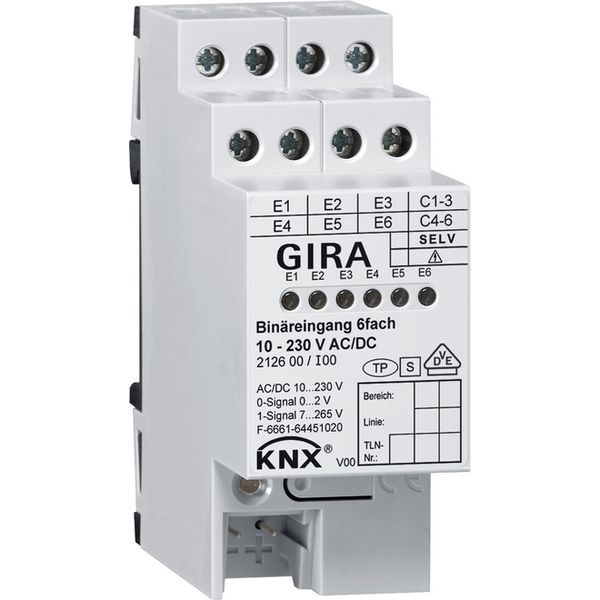
bin.input 6-g 10 - 230 V AC/DC KNX DRA
Ir noliktavā: Nē
Piegādātāja krājumi: Nē
Minimālais pasūtījuma daudzums: 1
Cena (bez PVN):
179,31 €
EAN: 4010337018834
MPN: 212600
Iepakojums: 1
Paredzamais piegādes laiks mūsu noliktavā (aptuveni):
4-6 weeks
Technical Information
| Preces stāvoklis | Jauns |
| Ražotāja nosaukums | bin.input 6-g 10 - 230 V AC/DC KNX DRA |
| Zīmols | Gira |
| Kategorijas |
Sensori
|
| Izcelsmes valsts | DE |
| Harmonizētās sistēmas kods | 8537 1091 00 |
| Montāžas metode | DRA (adapteris uz DIN sliedes) |
| Ievadu skaits | 6 |
| Autobusu sistēma KNX | Yes |
| Autobusu sistēmas radio bieži | No |
| Autobusu sistēma Powernet | No |
| Ar autobusa savienojumu | - |
| Platums moduļu atstarpju skaitā | 2 |
| Sprieguma veids (ieejas spriegums) | AC/DC |
| Nepieciešams ārējā signāla spriegums | - |
| Citas autobusu sistēmas | Nav |
| Autobusu sistēma LON | No |
| Ieejas spriegums | 10-230 V |
| LED vadība | - |
| Aizsardzības pakāpe (IP) | IP20 |
| Ar LED indikāciju | Yes |
| Autobusu sistēma KNX radio | No |
| Radio bieži divvirzienu | - |
| Autobusa modulis noņemams | - |
| Min. iebūvētās instalācijas kastes dziļums | 0 mm |
Iepakojuma informācija
| Iepakojuma līmenis 1 | 4010337018834 |
Apraksts
Binary input, 6-gang 10 - 230 V AC DC for KNX DRA plus DRA binary inputs for connecting contacts. The switching processes of contacts (e.g. security light button) are converted to KNX telegrams. The inputs can be assigned various functions or blocked independently of each other in the process. Signal display possible via yellow status LEDs. Features: Each input has full function. All channel-oriented functions can be parameterised separately per input. Actively transmitting telegrams of inputs can be delayed globally based on bus voltage return or ETS programming. Debounce and telegram rate limit are configurable. Free assignment of the functions switching, dimming, blind, value transmitter and pulse counter to the inputs. Blocker for blocking individual inputs (polarity of the blocking object adjustable) for the functions switching, dimming, blind and value transmitter. Behaviour upon bus voltage recovery can be configured separately for each input. Switching function: Two independent switching objects are available for each input (switching commands can be individually configured), command for leading and trailing edge can be set independently (ON, OFF, CHANGE, no reaction), independent cyclical transmission of the switching object depending on the edge or depending on the object value can be selected. Dimming function: single and double-surface operation, time between dimming and switching and dim-step size can be set, telegram repetition and stop-telegram transmission possible. Blind function: Command can be set with rising edge (no function, UP, DOWN, CHANGE), operating concept can be configured (Step - Move - Step or Move - Step), time between short and long-term operation can be set (only with Step - Move - Step), slat adjustment time can be set. Value transmitter function: edge (button as NO contact, button as NC contact, switch) and value with edge can be configured, value adjustment with button by pressing and holding button for value transmitters possible, light scene auxiliary unit with memory function and saving of the scene without previously calling up is possible. Pulse counter function: Counting interval is adjustable, edges (counting with leading edge, counting with trailing edge, counting with leading and trailing edge) are programmable, number of pulses required at the input can be configured, number of required counts for a counter change can be configured, each input includes a main counter and an intermediate counter, main counter and intermediate counter can operate separately from each other as a forward or reverse counter, start and end values of the counter can be set via parameter or communication object, count status can be read via KNX or automatically, performance after counter operation is programmable, reset pulse counter via KNX (counter reset). The binary input has six independent inputs in the voltage range of 10 to 230 V that are connected to the electrical signals. Inputs 1 to 3 and inputs 4 to 6 share one common reference potential. Therefore different external conductors can be connected for each input group, e.g.: E1-E3 = L1 and E4-E6 = L2. Evaluation of direct current voltage signals (DC) or alternating current voltage signals (AC).

