Reģistrējieties, lai atbloķētu savas ekskluzīvās B2B cenas un sāktu iepirkties. Reģistrējieties tagad!
RS485 bus actuator heating/cooling relay
Ir noliktavā: Nē
Piegādātāja krājumi: Nē
Minimālais pasūtījuma daudzums: 1
Cena (bez PVN):
48,18 €
EAN: 4010312313824
MPN: 30014014
Iepakojums: 1
Paredzamais piegādes laiks mūsu noliktavā (aptuveni):
2-4 weeks
Technical Information
| Preces stāvoklis | Jauns |
| Ražotāja nosaukums | RS485 bus actuator heating/cooling relay |
| Zīmols | ELTAKO |
| Kategorijas |
Sensori
|
| Izcelsmes valsts | CN |
| Harmonizētās sistēmas kods | 8526 9200 00 |
| Montāžas metode | DRA (adapteris uz DIN sliedes) |
| Izvadu skaits | 2 |
| Maks. izejas strāva | 4 A |
| Maks. pārslēgšanas strāva (pretestības slodze) | 4 A |
| Autobusu sistēma KNX | No |
| Autobusu sistēmas radio bieži | Yes |
| Autobusu sistēma Powernet | No |
| Ar autobusa savienojumu | Yes |
| Platums moduļu atstarpju skaitā | 1 |
| Citas autobusu sistēmas | Nav |
| Autobusu sistēma LON | No |
| Pārslēgšanas spriegums | 230 V |
| Aizsardzības pakāpe (IP) | IP20 |
| Koriģējošs mainīgais konsekvents | Yes |
| Mainīgo komutācijas koriģēšana | Yes |
| Vārstu aizsardzības funkcija | No |
| Manuālais slēdzis | Yes |
| Autobusu sistēma KNX radio | No |
| Radio bieži divvirzienu | Yes |
| Autobusa modulis noņemams | Yes |
Iepakojuma informācija
| Iepakojuma līmenis 1 | 4010312313824, 4010312313824 |
| Iepakojuma līmenis 2 | 4010312313824 |
| Iepakojuma līmenis 3 | 4010312313824 |
Lejupielādes
Apraksts
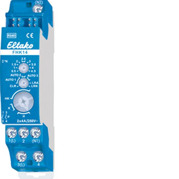
Heating/cooling relay, 1+1 NO contacts potential free 4A/250V AC, with DX technology. Bidirectional. Only 0.1 watt standby loss. Modular device for DIN-EN 60715 TH35 rail mounting. 1 module = 18mm wide, 58mm deep. Connection to the Eltako-RS485 bus. Bus cross wiring and power supply with jumper. Patented Eltako Duplex technology allows you to switch normally potential free contacts in zero passage switching when 230V A/C voltage 50Hz is switched. This drastically reduces wear. To achieve this, simply connect the N conductor to the terminal (N1) and L to 1(L) and/or N to (N2) and L to 3(L). This results in an additional standby consumption of only 0.1 watt. When both relays of the FHK14 are switched on, 0.4 watts are required. If supply voltage fails, the device is switched off in defined mode. This heating/cooling relay assesses information about wireless temperature controllers or sensors. Possibly supplemented by window/door contacts, motion detectors, window handle sensor FFG7B-rw and wireless pushbuttons. As an alternative to a wireless temperature controller, the temperature information on the set and actual values can be obtained from a Professional Smart Home controller. It is also possible to specify the set temperature via the Professional Smart Home controller and thus limiting the setting range of the wireless temperature controller. Top rotary switch for adjustable hysteresis: Left stop: lowest hysteresis 0.5º. Middle position: hysteresis 2.5º. Right stop: largest hysteresis 4.5º. Inbetween, divisions in steps of 0.5º. Middle rotary switch for regulation types: AUTO 1: With PWM control at T = 4 minutes. (PWM = pulse width modulation). (suitable for valves with thermoelectric valve drive). AUTO 2: With PWM control at T = 15 minutes. (suitable for valves with motor-driven valve drive). AUTO 3: With 2-point control. Bottom rotary switch for operating modes: H: heating mode (Contact 1-2 and Contact 3-4). K: cooling mode (Contact 1-2 and Contact 3-4). HK: heating mode (Contact 3-4) and cooling mode (Contact 1-2). In heating mode, the frost protection function is always enabled. As soon as the actual temperature drops below 8°C, the temperature is controlled in the selected operating mode to 8°C. If one or several windows are open, the output remains off provided the window/door contacts FTK or window handle sensors FFG7B-rw are taught-in. In heating mode, however, the frost protection remains enabled. As long as all taught-in motion detectors FBH detect no motion, the device is switched to setback mode. In heating mode, the reference temperature is set back by 2°. In cooling mode, it is raised by 2°. As soon as a motion detector signals movement again, the device is switched to normal mode. When a wireless pushbutton FT4 is taught-in, the assignment of the 4 keys is assigned with the following fixed functions: Top right: Normal mode (can also be enabled by timer). Bottom right: Night setback mode by 4°. In cooling mode, raised by 4° (can also be enabled by timer). Top left: Setback mode by 2°, in cooling mode, raised by 2°. Bottom left: Off (in heating mode, frost protection enabled. In cooling mode permanent off). If the motion detector and wireless pushbutton are taught-in at the same time, the last telegram received is always the one that is valid. A motion detector therefore switches off a setback mode selected by wireless pushbutton when a movement is detected. The LED below the upper function rotary switch performs during the teach-in process according to the operating instructions. It shows control commands by short flickering during operation.

