Reģistrējieties, lai atbloķētu savas ekskluzīvās B2B cenas un sāktu iepirkties. Reģistrējieties tagad!
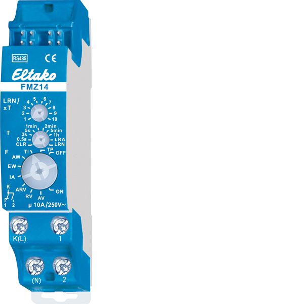
RS485 bus actuator multifunction time relay
Ir noliktavā: Nē
Piegādātāja krājumi: Nē
Minimālais pasūtījuma daudzums: 1
Cena (bez PVN):
45,37 €
EAN: 4010312313787
MPN: 30014009
Iepakojums: 1
Technical Information
| Preces stāvoklis | Jauns |
| Ražotāja nosaukums | RS485 bus actuator multifunction time relay |
| Zīmols | ELTAKO |
| Kategorijas |
Sensori |
| Izcelsmes valsts | CN |
| Harmonizētās sistēmas kods | 8526 9200 00 |
| Montāžas metode | DRA (adapteris uz DIN sliedes) |
| Nominālā strāva | 10 A |
| Izejas jauda | 2000 W |
| Nominālais darba spriegums | 12 V |
| Autobusu sistēma KNX | No |
| Autobusu sistēmas radio bieži | Yes |
| Autobusu sistēma Powernet | No |
| Maks. pārslēgšanas jauda | 2000 W |
| Ar autobusa savienojumu | Yes |
| Maks. pārslēgšanas kontaktu skaits | 1 |
| Platums moduļu atstarpju skaitā | 1 |
| Maks. pārslēgšanas strāva | 10 A |
| Citas autobusu sistēmas | Nav |
| Autobusu sistēma LON | No |
| Piemērots C-slodzei | - |
| Savienojamas dažādas fāzes | No |
| Vietējā darbība/rokas darbība | No |
| Aizsardzības pakāpe (IP) | IP20 |
| Ar LED indikāciju | No |
| Moduļu paplašināšana | No |
| Autobusu sistēma KNX radio | No |
| Radio bieži divvirzienu | Yes |
| Autobusa modulis noņemams | Yes |
| Maks. pārslēgšanas jaudas LED | 400 W |
Iepakojuma informācija
| Iepakojuma līmenis 1 | 4010312313787, 4010312313787 |
| Iepakojuma līmenis 2 | 4010312313787 |
| Iepakojuma līmenis 3 | 4010312313787 |
Lejupielādes
Apraksts
Multifunction time relay with 10 functions, 1 CO contact potential free 10A/250V AC, 230V LED lamps up to 400W, incandescent lamps 2000 watts*, with DX technology. Bidirectional. Only 0.4 watt standby loss. Modular device for DIN-EN 60715 TH35 rail mounting. 1 module = 18mm wide, 58mm deep. Connection to the Eltako-RS485 bus. Bus cross wiring and power supply with jumper. Wireless window contacts (FTK) at opened windows with the function NO or NC can be taught-in. If a direction switch is taught-in, a function (e.g. TI) can be started using the top switch (START) and stopped with the bottom switch (STOP). Patented Eltako Duplex technology allows you to switch normally potential free contacts in zero passage switching when 230V A/C voltage 50Hz is switched. This drastically reduces wear. To achieve this, simply connect the N conductor to the terminal (N) and L to K(L). This results in an additional standby consumption of only 0.1 watt. If supply voltage fails, the two contacts switch off. When power is restored, contact 1 closes. Time setting between 0.5 second and 10 hours. Teach-in takes place using the top and middle rotary switches and then the time is set. T is the time base and xT the multiplier. The function is selected using the bottom rotary switch: RV = off delay. AV = operate delay. TI = clock generator starting with impulse. TP = clock generator starting with pause. IA = impulse controlled operate delay (e.g. automatic door opener). EW = fleeting NO contact. AW = fleeting NC contact. ARV = operate and release delay. ON = Permanent ON. OFF = Permanent OFF. The LED below the upper function rotary switch performs during the teach-in process according to the operating instructions. It shows control commands by short flickering during operation. *The maximum load can be used starting at a delay time or clock cycle of 5 minutes. The maximum load will be reduced for shorter times as follows: up to 2 seconds 15%, up to 2 minutes 30%, up to 5 minutes 60%.

