Reģistrējieties, lai atbloķētu savas ekskluzīvās B2B cenas un sāktu iepirkties. Reģistrējieties tagad!
Powerline actuator 2 channels with 2 sensor inputs
Ir noliktavā: Nē
Piegādātāja krājumi: Nē
Minimālais pasūtījuma daudzums: 1
Cena (bez PVN):
95,61 €
EAN: 4010312316672
MPN: 31200001
Iepakojums: 1
Paredzamais piegādes laiks mūsu noliktavā (aptuveni):
2-4 weeks
Technical Information
| Preces stāvoklis | Jauns |
| Ražotāja nosaukums | Powerline actuator 2 channels with 2 sensor inputs |
| Zīmols | ELTAKO |
| Kategorijas |
Sensori
|
| Izcelsmes valsts | CN |
| Harmonizētās sistēmas kods | 8526 9200 00 |
| Montāžas metode | Iebūvējams vienā līmenī (apmetums) |
| Nominālā strāva | 5 A |
| Izejas jauda | 1000 W |
| Nominālais darba spriegums | 230 V |
| Autobusu sistēma KNX | No |
| Autobusu sistēmas radio bieži | No |
| Autobusu sistēma Powernet | Yes |
| Maks. pārslēgšanas jauda | 1000 W |
| Ar autobusa savienojumu | Yes |
| Maks. pārslēgšanas kontaktu skaits | 2 |
| Maks. pārslēgšanas strāva | 5 A |
| Citas autobusu sistēmas | Nav |
| Autobusu sistēma LON | No |
| Piemērots C-slodzei | Yes |
| Savienojamas dažādas fāzes | No |
| Vietējā darbība/rokas darbība | Yes |
| Ar LED indikāciju | Yes |
| Moduļu paplašināšana | No |
| Autobusu sistēma KNX radio | No |
| Radio bieži divvirzienu | No |
| Autobusa modulis noņemams | No |
| Min. iebūvētās instalācijas kastes dziļums | 25 mm |
Iepakojuma informācija
| Iepakojuma līmenis 1 | 4010312316672, 4010312316672 |
| Iepakojuma līmenis 2 | 4010312316672 |
| Iepakojuma līmenis 3 | 4010312316672 |
Lejupielādes
Apraksts
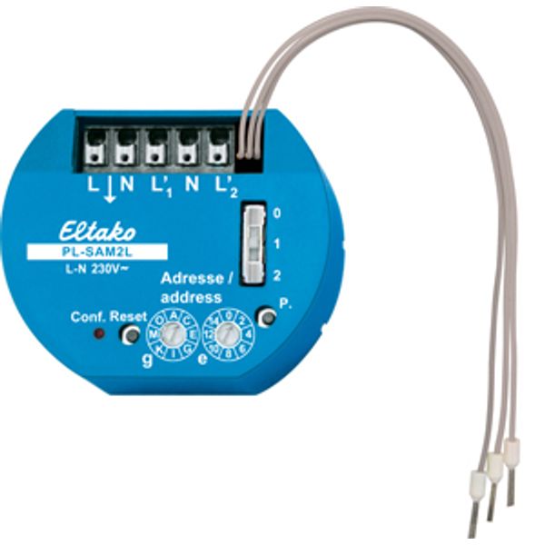
Powerline actuator with 2 channels. 53x43mm, 25mm deep for mounting in 58mm switch boxes. Used as impulse switch or relay. 1+1 NO contacts not potential free 5A/250V AC, incandescent lamps 1000 watts. 2 sensor inputs with internal low voltage. Standby loss only 0,5 watt. To control and switch at the same place. Use only potential free switching elements. Internal low voltage applied to the sensor inputs. Two rotary switches are located on the front for address assignment: The left rotary switch defines the group address g with 16 alphabetical values from A to P. The right rotary switch defines the element address e with 16 numerical values from 0 to 15. Above it is a slide switch which acts as a configuration switch with positions 0, 1 and 2. Position 0: Sensor inputs function as pushbuttons (impulse switches). Position 1: Sensor input functions as NC contact (relay). Position 2: A change-over switch is evaluated as a pushbutton. All entries and configurations can also be accessed via the mains using the PC software SIENNA Professional. This means that another configuration can also be set that is not available via the rotary switches: Position 3: Sensor input acts as NO contact (relay inverse). To the left of the rotary switches is a red LED which indicates all activities. Next to it is a reset pushbutton and to the right of that is a service pin. For functions, please refer to the operating instructions. The terminals located above are plug-in terminals for conductor cross-sections of 0.2mm² to 1.5mm². Next to them are three wires with wire end-sleeves for the two control inputs with internal low voltage.

