Зарегистрируйтесь, чтобы разблокировать ваши эксклюзивные B2B цены и начать покупки. Зарегистрируйтесь сейчас!
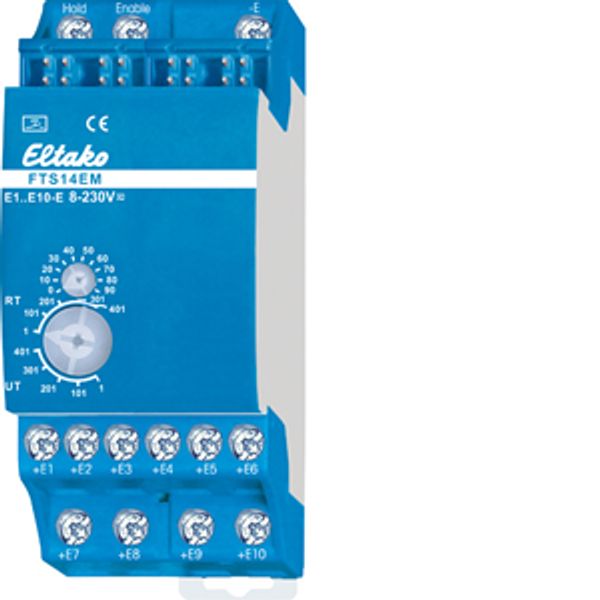
RS485 bus pushbutton input module
В наличии: Нет
Запасы поставщика: Нет
Минимальное количество заказа: 1
Цена (без НДС):
57,13 €
EAN: 4010312315071
MPN: 30014060
Упаковка: 1
Ориентировочное время доставки на наш склад (приблизительно):
2-4 weeks
Technical Information
| Состояние товара | Новый |
| Название производителя | RS485 bus pushbutton input module |
| Бренд | ELTAKO |
| Категории |
Датчики
|
| Страна происхождения | CN |
| Код гармонизированной системы | 8526 9200 00 |
| Способ крепления | DRA (адаптер для установки на DIN-рейку) |
| Шинная система KNX | No |
| Шинная система радио частая | Yes |
| Шинная система Powernet | No |
| Тип крепления | Крепление на зажимах |
| Ширина в количестве модульных интервалов | 2 |
| Другие автобусные системы | Другое |
| Шинная система LON | No |
| Степень защиты (IP) | IP20 |
| Количество точек срабатывания | 10 |
| Шинная система Радио KNX | No |
| Радио частый двунаправленный | Yes |
Сведения об упаковке
| Уровень упаковки 1 | 4010312315071, 4010312315071 |
| Уровень упаковки 2 | 4010312315071 |
| Уровень упаковки 3 | 4010312315071 |
Загрузки
Описание
Input module for the Eltako RS485 bus, 10 control inputs for universal control voltage. Only 0.1 watt standby loss. Modular device for DIN-EN 60715 TH35 railmounting. 2 modules = 36mm wide, 58mm deep. Connection to the Eltako-RS485 bus. Bus cross wiring and power supply with jumper. Operation in conjunction with FAM14 or FTS14KS. 10 control inputs +E1 to +E10/-E electrically isolated from the supply voltage. Control voltage: 8..230V UC. The control inputs can be either activated for pushbuttons (delivery state), window-door contacts or motion detectors. From the production week 21/19 the signals of the control inputs can be inverted. Control inputs for pushbuttons: telegrams of pushbuttons will be generated (e.g. 0x70). Each FTS14EM can be set to UT (= universal pushbutton) or RT (= direction pushbutton) on the lower rotary switch. Control inputs for window-door contacts: telegrams of the window-door contact FTK are generated (EEP D5-00-01). If the input is driven by the contact with the control voltage to be applied externally, the telegram window open is generated. If the contact is opened, the telegram window open is generated. As with the wireless sensor FTK, the status telegram is repeated every 15 minutes. Control inputs for motion detectors: telegrams of the wireless motion/brightness sensor FBH are generated (EEP A5-08-01), wherein the brightness value is always 0. If the input is driven by the contact with the control voltage to be applied externally, the telegram motion is generated. If the contact is opened, the telegra no motion will be generated. As with the wireless sensors FBH, the status telegram is repeated every 15 minutes. Each telegram of a contact input has to be taught-in with an identification number (ID) into one or more actuators according to the operating instructions. The lower rotary switch defines the group to which an FTS14EM belongs. A total of 5 groups are available (1, 101, 201, 301 and 401) each with 100 IDs. The upper rotary switch (0 to 90) sets the ID within a group. The ID range within a group results from the combination of upper and lower rotary switches and must be set differently on each FTS14EM. Maximum ten FTS14EMs form a group. Therefore, a total of 50 FTS14EMs comprising 500 pushbuttons or contacts are possible in one RS485 bus. To generate the necessary teach-in telegrams for teaching-in into the actuators, the requested group has to be selected on the upper and lower rotary switch. For pushbuttons in the range UT or RT or for window-door contacts and motion sensors in the range RT. Then confirm the required control input. In operation, the same group should be selected for window-door contacts and motion sensors in the range UT or RT for pushbutton or UT. The LED below the upper rotary switch flashes briefly, when a connected contact is closed. Optional: An FAM14 wireless antenna module (from Wireless Building System) which is only two modules wide can also be installed. Actuators can then be activated via the FTS14EM by wireless pushbuttons and contacts, handheld transmitters and wireless sensors in addition to conventional buttons. As the FAM14 has an integrated switch mode power supply unit, the FTS14KS is no longer required for power supply in this configuration. The bidirectional FAM14 also permits a Smart Home central unit SafeIV to evaluate feedback messages from the actuators transferred by wireless. Each actuator status is then displayed and can also be changed. Connecting the HOLD terminals of all devices regulates bus access and prevents collisions. The telegrams of the FTS14EM can also be sent to the Eltako Wireless Building with the optional wireless output module FTS14FA.

