Registreeru, et avada oma eksklusiivsed B2B hinnad ja alustada ostlemist. Registreeru kohe!
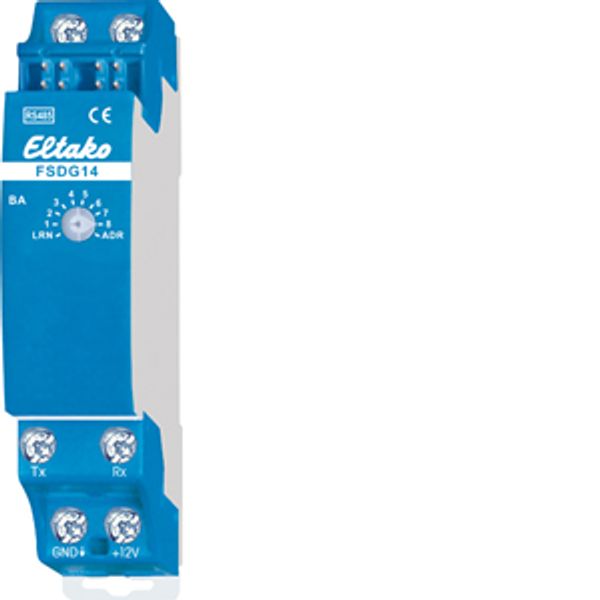
RS485 bus energy meter data gateway
Laos: Ei
Hankija laovaru: Ei
Minimaalne tellimuse kogus: 1
Hind (ilma KM-ta):
47,03 €
EAN: 4010312316146
MPN: 30014066
Pakend: 1
Hinnanguline tarneaeg meie laos (umbes):
Päringu alusel
Technical Information
| Toote seisukord | Uus |
| Tootja nimi | RS485 bus energy meter data gateway |
| Bränd | ELTAKO |
| Kategooriad |
Andurid
|
| Päritoluriik | CN |
| Harmoneeritud süsteemi kood | 8526 9200 00 |
| Paigaldusviis | DRA (DIN liistule) |
| Mudel | Raadioliides, tootjapõhine |
| Pinge liik | DC |
| Võimsustarve | 0.4 W |
| Siinisüsteem KNX | No |
| Raadiosageduslik siinisüsteem | Yes |
| Siinisüsteem Powernet | No |
| Laius mooduli arvudes | 1 |
| Muud siinisüsteemid | Muul viisil |
| Siinisüsteem LON | No |
| Lahtimonteerimise kaitse | No |
| Raadioliides | No |
| Infrapunaliides | Yes |
| Protokoll | Muul viisil |
| Sõltuvalt tarnijast | No |
| Uuendatav | No |
| Visualiseerimine | No |
| Veebiserver | No |
| Talitluspinge | 12 V |
| Kaitseaste (IP) | IP20 |
| LED näidikuga | No |
| Siinisüsteem KNX radio | No |
| Raadiosageduslik, kahesuunaline | Yes |
Pakendamise üksikasjad
| Pakkimistase 1 | 4010312316146, 4010312316146 |
| Pakkimistase 2 | 4010312316146 |
| Pakkimistase 3 | 4010312316146 |
Allalaadimised
Kirjeldus
Wireless energy meter data gateway for meters equipped with an IEC 62056-21 IR interface. 2 channels. Only 0.4 watt standby loss. Modular device for DIN-EN 60715 TH35 rail mounting. 1 module = 18mm wide, 58mm deep. Connection to the Eltako-RS485 bus. Bus cross wiring and power supply with jumper. This energy meter data gateway can provide the data of an electronic domestic supply meter (eHZ-EDL) with IR interface according to IEC 62056-21 and SML protocol version 1 to the RS485 bus. Either for forwarding to an external computer or a Professional Smart Home controller. Regular flashing of the green LED indicates that the FSDG14 is receiving data from the meter. Active power, up to 4 meter readings and the serial number are transferred. The serial number corresponds to the last 4 bytes (hex) of the server ID printed on the meter. The telegram is sent over the wireless building service by means of the wireless antenna module FAM14. Usage data are transmitted over channel 1 and delivery data over channel 2. It is therefore essential for the FAM14 to issue a device address. If there is a change in active power or a meter reading, the appropriate telegram is sent immediately and all telegrams including the serial number are sent cyclically every 10 minutes. The PCT14 PC tool can also read out the FSDG14. Turn the rotary switch to select the following operating modes (OBIS codes according to IEC 62056-61): 1: Usage meter (1.8.0) and usage power on channel 1, delivery meter (2.8.0) and delivery power on Channel 2. 2: Usage tariff 1 (1.8.1) and tariff 2 (1.8.2) and usage power on channel 1, delivery tariff 1 (2.8.1) and tariff 2 (2.8.2) and delivery power on channel 2. 3: Usage tariff 1 (1.8.1) and tariff 2 (1.8.2) and usage power on channel 1, delivery meter (2.8.0) and delivery power on Channel 2. 4: Usage meter (1.8.0) and usage power on channel 1, delivery tariff 1 (2.8.1) and tariff 2 (2.8.2) and delivery power on channel 2. The link is made by using an AIR IR scanner. The scanner is attached by its fixing magnets to the IR output of the meter and is connected by its connecting cable to terminals Rx, GND and +12 V.
Tarvik

In stock: No
ELTAKO
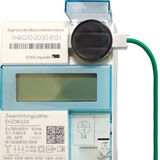
IR scanner for energy meters data gateway
87,66 €
EAN: 4010312316153
MPN: 30000970
Pakend: 1

