Register to unlock your exclusive B2B prices and start shopping. Sign up now!
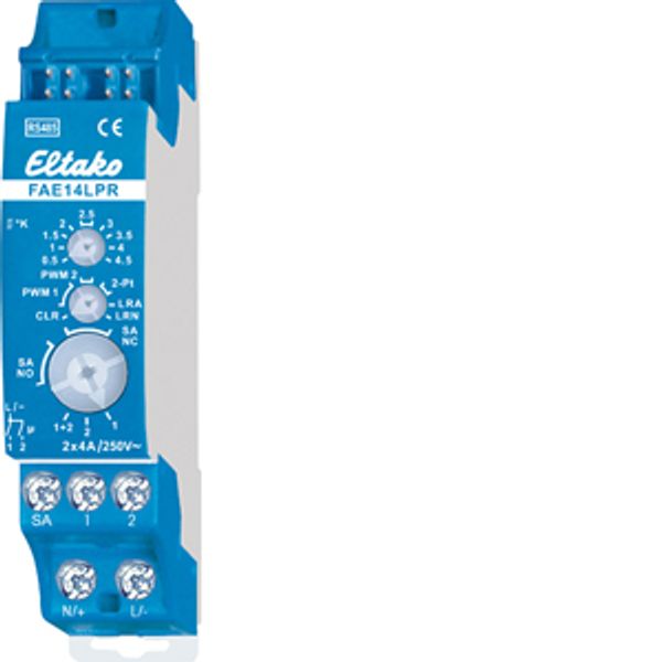
RS485 bus actuator single room control, heating/cooling for 2 zones with PCB relay
In stock: No
Vendor stock: No
Minimal order quantity: 1
Price (excl. VAT):
48,81 €
EAN: 4010312314234
MPN: 30014030
Package: 1
Technical Information
| Item condition | New |
| Manufacture name | RS485 bus actuator single room control, heating/cooling for 2 zones with PCB relay |
| Brand | ELTAKO |
| Categories |
Sensors |
| Country of origin | CN |
| Harmonized System Code | 8526 9200 00 |
| Mounting method | DRA (DIN-rail adapter) |
| Number of outputs | 2 |
| Max. switching current (resistive load) | 4 A |
| Bus system KNX | No |
| Bus system radio frequent | Yes |
| Bus system Powernet | No |
| With bus connection | Yes |
| Width in number of modular spacings | 1 |
| Other bus systems | None |
| Bus system LON | No |
| Switching voltage | 230 V |
| Degree of protection (IP) | IP20 |
| Correcting variable consistent | Yes |
| Correcting variable switching | Yes |
| Valve protection function | No |
| Manual switch | Yes |
| Bus system KNX radio | No |
| Radio frequent bidirectional | Yes |
| Bus module detachable | No |
Packing details
| Packing level 1 | 4010312314234, 4010312314234 |
| Packing level 2 | 4010312314234 |
| Packing level 3 | 4010312314234 |
Downloads
Description
2-channel single room control, 4A/250V, potential free. Bidirectional. Only 0.1 watt standby loss. Modular device for DIN-EN 60715 TH35 rail mounting. 1 module = 18mm wide, 58mm deep. Connection to the Eltako-RS485 bus. Bus cross wiring and power supply with jumper. If both relays are switched on, a power of 0.4 watts is required. The channels can be taught-in together at the same time. Use the lower rotary switch in positions 1+2. Alternatively, they can be taught-in separately in position 1 or 2. First teach in the sensors using the rotary switches. In normal mode, set the operating mode using the middle rotary switch. PWM 1 for valves with thermoelectric actuator, T = 4 minutes. PWM 2 for valves with motor-driven actuator, T = 15 minutes. 2-Pt for 2-point control. PWM control mode: The upper rotary switch sets the required temperature difference at which the device is switched on at 100%. When the actual temperature >= reference temperature, the device is switched off. When the actual temperature <= (reference temperature – hysteresis), the device is switched on at 100%. When the actual temperature is between (reference temperature – hysteresis) and the reference temperature, the device is switched on and off by a PWM in steps of 10% depending on the temperature difference. The lower the temperature difference, the shorter the switch-on time. As a result of the settability of the 100% value, the PWM can be adapted to the radiator size and inertia. The signs are the opposite in cooling mode. In heating mode, the frost protection function is always enabled. As soon as the actual temperature drops below 8°C, the temperature is controlled in the selected operating mode to 8°C. Two-point control mode: The upper rotary switch sets the required difference between the switch-on and switch-off temperatures. When the actual temperature >= reference temperature, the device is switched off. When the actual temperature <= (reference temperature – hysteresis), the device is switched on. The signs are the opposite in cooling mode. The type of connected actuators will be selected with the lower rotary switch. SA NC for actuator NC (normally closed) or SA NO for actuator NO (normally open). When wireless window/door contacts FTK or window handle sensors FFG7B are taught-in, they are OR linked. If one or more windows are open, the output remains off. In heating mode, however, the frost protection remains enabled. When motion detectors FBH are taught-in, they are AND linked. If all FBHs signal No motion, the device switches to standby setback mode: In heating mode, the reference temperature is set back by 2°. In cooling mode, it is raised by 2°. As soon as a motion detector signals movement again, the device is switched to normal mode. When the FBHs and wireless pushbuttons are taught-in, the last telegram received is always the one that is valid. An FBH therefore switches off a setback mode selected by means of the wireless pushbutton when motion is detected. When a wireless pushbutton is taught-in, the 4 keys are assigned the following functions: Top right: Normal mode (can also be enabled by timer with the function ON). Bottom right: Night setback mode by 4°. In cooling mode: increase by 4° (can also be enabled by timer with the function OFF). Top left: Standby setback mode by 2°, in cooling mode, increase by 2°. Bottom left: Off (in heating mode, frost protection enabled. In cooling mode permanent off). Malfunction mode: If no wireless telegram will be received from a temperature sensor for more than 1 hour, the LED lights up and it will be switched to fault mode: in heating mode it will be switched on for 1.2 minutes and switched off for 2.8 minutes at PWM 1. At PWM 2 and 2-Pt the times are 4.5 minutes on and 10.5 minutes off. The device is switched off in cooling mode. When a wireless telegram is again received, the LED goes out and the device switches back to normal mode. The LED below the upper function rotary switch performs during the teach-in process according to the operating instructions. It shows control commands by short flickering during operation.

