Register to unlock your exclusive B2B prices and start shopping. Sign up now!
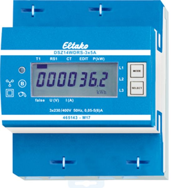
RS485 bus wireless three-phase energy meter, MID approval
In stock: No
Vendor stock: No
Minimal order quantity: 1
Price (excl. VAT):
164,96 €
EAN: 4010312501450
MPN: 28305712
Package: 1
Estimate delivery time at our warehouse (approx.):
By request
Technical Information
| Item condition | New |
| Manufacture name | RS485 bus wireless three-phase energy meter, MID approval |
| Brand | ELTAKO |
| Categories |
Electric meters
|
| Country of origin | CN |
| Harmonized System Code | 9028 3019 00 |
| Mounting method | DRA (DIN-rail adapter) |
| Width | 70 mm |
| Height | 82 mm |
| Depth | 58 mm |
| Frequency | 50 Hz |
| Max. current (Imax) | 6 A |
| Width in number of modular spacings | 4 |
| Degree of protection (IP) | IP20 |
| Pole type | Four conductor |
| Nominal voltage (Un) N-L | 230 V |
| Nominal current (In) | 5 A |
Packing details
| Packing level 1 | 4010312501450, 4010312501450 |
| Packing level 2 | 4010312501450 |
Other Technical data
| Model | Measurement transformer |
| Suitable for | Purchase |
| Type of indication | Digital |
| Number of positions total (counter) | 7 |
| Type of meter | Electronic |
| Type of interface | RS-485 |
| Energy type | Effective power |
| Tariff type | One-tariff |
| Tariff control | External |
| Escapement mechanism | Yes |
| Calibrated | Yes |
| Approval | Measuring Instruments Directive |
| Accuracy class | B |
| Measurement type load profile | - |
| EEC40 signature | - |
| With lock code | - |
| Nominal voltage (Un) L-L | 400 V |
Downloads
Description
RS485 bus wireless three-phase energy meter with settable CT ratio and MID. Maximum current 3x5A. Standby loss 0.8W at L1 and only 0.5 W at L2 and L3 each. Modulair device for DIN-EN 60715 TH35 rail mounting in distribution cabinets with IP51 protection class. 4 modules = 70mm wide and 58mm deep. Accuracy class B (1%). With RS485 interface. This three-phase energy meter measures active energy by means of the current between input and output. The internal power consumption of 0.8W or 0.5W active power per path is neither metered nor indicated. 1, 2 or 3 phase conductors with max. currents up to 5 A can be connected. The inrush current is 10mA. The terminals L1 and N must always be connected. Connection to the Eltako RS485 bus via a FBA14 by means of a 2-wire screened bus line (e.g. telephone line). The meter reading and the momentary capacity are transferred to the bus – e.g. for transfer to an external computer or a Professional Smart Home controller – and is also transferred to the wireless network via the FAM14. For this it is necessary that a device address is assigned from the wireless antenna module FAM14, according to the operating instructions. The 7 segment LC display is also legible twice within a period of 2 weeks without power supply. The power consumption is displayed with a LED flashing 10 times per kWh next to the display. On the right next to the display are the keys MODE and SELECT. Press them to scroll through the menu. First the background lighting switches on. The display then shows the total active energy, the active energy of the resettable memory as well as the instantaneous values of consumption, voltage and current per phase. The CT ratio can also be set. It is set to 5:5 at the factory and blocked with a bridge over the terminals which are marked with 'JUMPER'. To adjust the CT ratio to the installed transformer remove the bridge and reset the energy meter according to the operation manual. Then block it again with the bridge. Adjustable current transformer ratios: 5:5, 50:5, 100:5, 150:5, 200:5, 250:5, 300:5, 400:5, 500:5, 600:5, 750:5, 1000:5, 1250:5 and 1500:5. Error message (false): When the phase conductor is missing or the current direction is wrong false and the corresponding phase conductor are indicated on the display. Important! Before working on the current transformers disconnect the voltage paths of the energy meters.

