Register to unlock your exclusive B2B prices and start shopping. Sign up now!
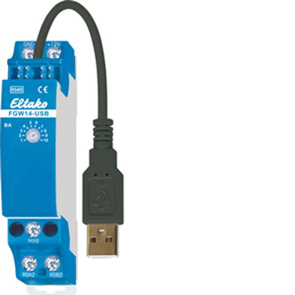
RS485 bus multiple gateway with USB-A connection
In stock: No
Vendor stock: No
Minimal order quantity: 1
Price (excl. VAT):
51,21 €
EAN: 4010312316054
MPN: 30014049
Package: 1
Estimate delivery time at our warehouse (approx.):
By request
Technical Information
| Item condition | New |
| Manufacture name | RS485 bus multiple gateway with USB-A connection |
| Brand | ELTAKO |
| Categories |
Sensors
|
| Country of origin | CN |
| Harmonized System Code | 8526 9200 00 |
| Mounting method | DRA (DIN-rail adapter) |
| Model | Multiple interface |
| Voltage type | DC |
| Power consumption | 0.3 W |
| Bus system KNX | No |
| Bus system radio frequent | Yes |
| Bus system Powernet | No |
| Width in number of modular spacings | 1 |
| Other bus systems | None |
| Bus system LON | No |
| Demounting protection | No |
| Radio interface | No |
| IR interface | No |
| Protocol | Other |
| Provider dependent | No |
| Updateable | No |
| Visualization | No |
| Web-Server | No |
| Operating voltage | 5 V |
| Degree of protection (IP) | IP20 |
| With LED indication | No |
| Bus system KNX radio | No |
| Radio frequent bidirectional | No |
Packing details
| Packing level 1 | 4010312316054, 4010312316054 |
| Packing level 2 | 4010312316054 |
| Packing level 3 | 4010312316054 |
Downloads
Description
Multiple gateway with USB-A connection. Bidirectional. Only 0.3 watt standby loss. Modular device for DIN-EN 60715 TH35 rail mounting. 1 module = 18mm wide, 58mm deep. The gateway is only 1 module wide but has multiple uses: To connect a Professional Smart Home controller or PC via a USB interface, to couple up to three FEM devices, for connection to the bus components of the older Series 12 or as a bus connector of two RS485 buses of Series 14. Connection to the Eltako-RS485 bus. Bus cross wiring and power supply with jumper. Operation in conjunction with FAM14 or FTS14KS. The Hold terminal is connected to the FAM14 or the FTS14KS. The PC is connected via a USB interface running at 9600 baud or 58 kbaud. Wireless receiver modules FEM are connected in parallel to the sub-bus terminals RSA2 and RSB2 as well as the power supply terminals GND and +12V. Up to 10 pushbutton input modules FTS12EM can be connected in series to the sub-bus terminals RSA2 and RSB2. If necessary in series with wireless receiver modules FEM. The Professional Smart Home controller or PC connection is via connection to the terminals Tx and Rx. Series 12 actuators are connected to the sub-bus terminals RSA2 and RSB2. There is no Hold connection in this case. A second Series 14 bus is fed into the terminals RSA2/RSB2. The settings of the operating mode rotary switch BA are carried out as described in the operating instructions.

