Register to unlock your exclusive B2B prices and start shopping. Sign up now!
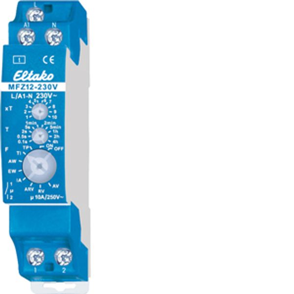
Analogue settable multifunction time relay, 1 NO contact 10A
In stock: No
Vendor stock: No
Minimal order quantity: 1
Price (excl. VAT):
41,85 €
EAN: 4010312603147
MPN: 23100530
Package: 1
Estimate delivery time at our warehouse (approx.):
2-4 weeks
Technical Information
| Item condition | New |
| Manufacture name | Analogue settable multifunction time relay, 1 NO contact 10A |
| Brand | ELTAKO |
| Categories |
Relays
|
| Country of origin | CN |
| Harmonized System Code | 8536 5080 00 |
| Mounting method | DIN rail |
| Function | Multi function |
| Built-in height | 58 mm |
| Type of excitation | Analogue with multi function |
| Width in number of modular spacings | 1 |
| Number of changeover switches | 0 |
| Control voltage 1 | 230 V |
| Type of control voltage 1 | AC |
| Frequency control voltage 1 | 50 Hz |
| Voltage type of supply voltage | AC |
| Supply voltage | 230 V |
| 1st interval unit | Minutes/hours |
| 1st interval | 0.1-40 |
| Nominal switching current at 250 V AC | 10 A |
| Switch capacity incandescent lamps | 1000 W |
| Switch capacity fluorescent lamp DUO | 500 VA |
| Switch capacity fluorescent lamp inductive | 500 VA |
| Switch capacity fluorescent lamp parallel | 250 VA |
| Number of contacts as normally closed contact | 0 |
| Number of contacts as normally open contact | 1 |
Packing details
| Packing level 1 | 4010312603147, 4010312603147 |
| Packing level 2 | 4010312603147 |
| Packing level 3 | 4010312603147 |
Downloads
Description
1 NO contact potential free 10A/250V AC. 230V LED lamps up to 200W, incandescent lamps 1000W*. Standby loss 0.4 watt only. Modular device for DIN-EN 60715 TH35 rail mounting. 1 module = 18mm wide, 58mm deep. Control voltage 230V. Supply voltage same as control voltage. Time setting between 0.1 second and 40 hours. Functions F: RV = off delay. AV = operate delay. TI = clock generator starting with impulse. TP = clock generator starting with pause. IA = impulse controlled operate delay (e.g. automatic door opener). EW = fleeting NO contact. AW = fleeting NC contact. ARV = operate and release delay. ON = permanent ON. OFF = permanent OFF. The LED below the big rotary switch indicates the contact position while time-out is in progress. It blinks while the relay contact is open, and is continuously ON as long as the relay contact is closed. The time base T is selected by means of the middle, latching rotary switch T. Time-base figures available are 0.1 seconds, 0.5 seconds, 2 seconds, 5 seconds, 1 minute, 2 minutes, 5 minutes, 1 hour, 2 hours and 4 hours. The total time is obtained by multiplying the timebase by the multiplier. The multiplier xT is set on the upper, latching rotary switch xT and is in the range from 1 to 10. Thus, time settings can be selected in the range from 0.1 second (time base 0.1 second and multiplier 1) and 40 hours (time base 4 hours and multiplier 10). * The maximum load can be used starting at a delay time or clock cycle of 5 minutes. The maximum load will be reduced for shorter times as follows: up to 2 seconds 15%, up to 2 minutes 30%, up to 5 minutes 60%.

